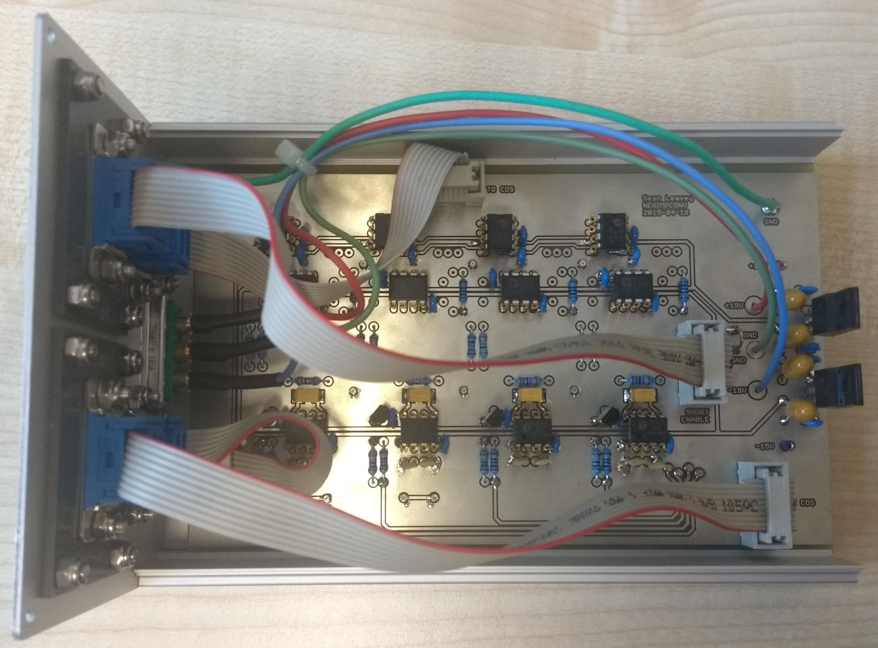
Negative impedance converter board, top view.
This board provides a means of improving the damping performance of suspended optics employing so-called eddy current dampers. This is a pretty standard technique employed for example in Advanced LIGO. The principle is that eddy currents are induced in the coils by the motion of magnets attached to the optics, and through the impedance of the coil wire this energy is converted from kinetic to heat. The damping of a standard coil-magnet attached to a coil driver can be improved by shorting the wires together, as presented in our paper. This board takes the idea one step further, presenting a negative impedance to the coils and therefore allowing very large currents to flow in the wires, providing greater dissipation.
Here are three videos demonstrating the effect. The first video shows suspension motion on a test optic without any damping (coils open). The high quality factor of the suspension means the optic swings at almost the same amplitude for the whole video (don't watch the whole thing - it's six minutes of swinging). The second video shows the effect of having the coil wires shorted together, as described in our paper. The damping is improved, with the ringdown taking about half the time of the undamped case. The last video shows the effect of using a negative impedance converter. The damping is dramatically improved, taking only seconds.
This technique is useful to provide damping on auxiliary optics in interferometers such as steering mirrors. It is likely that using the maximum damping effect will not provide a real benefit to sensitivity since it instead couples suspension platform motion to the optic, but with some tuning of the feedback you can obtain a sweet spot in damping and isolation.
The board provides inputs and outputs to allow the negative impedance compensation to be provided via our LIGO-style control system, CDS. For other applications it is possible to compensate the coil impedance using resistors, for which there are unpopulated sockets (R6, R13, R20, R27).
More details can be found in this poster I presented at the LVC Meeting in Maastricht, September 2018.
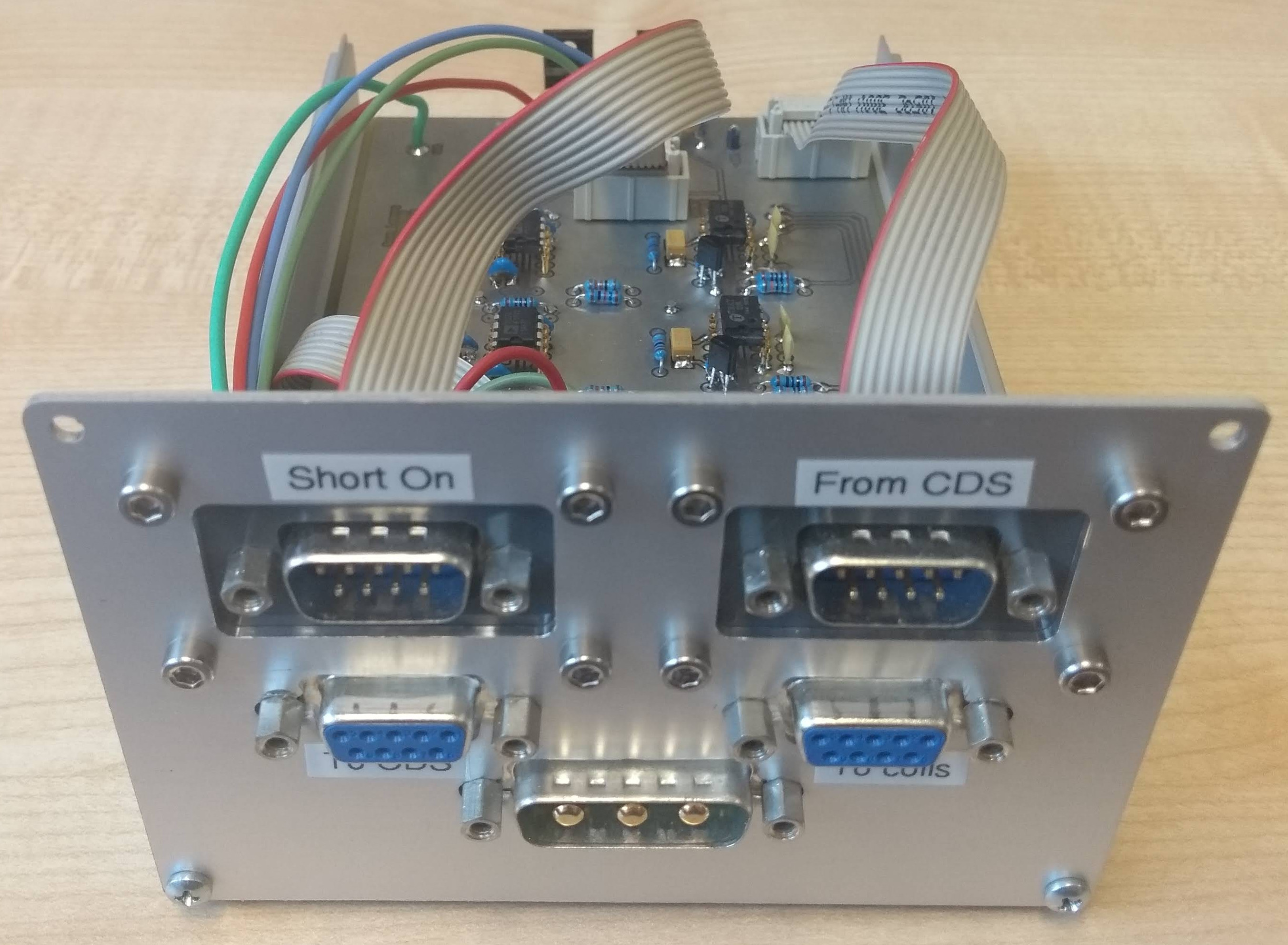
Negative impedance converter board, front view, with connectors for the coils, input and output for the feedback via CDS, and a digital input to short the coils.