This is an ethernet connected dust, temperature, humidity, pressure and light sensor.
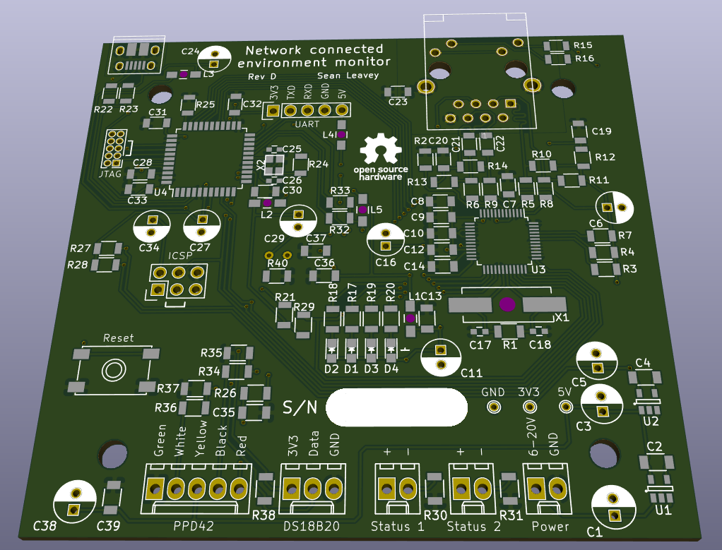
A 3D rendering of the environment sensor board, but without components (I upgraded to a new KiCad release which changed the 3D model names for the parts...)
I made this board mainly to learn about networking on the physical layer, using ethernet. Ethernet connections aren't trivial, especially high speed ones. They are inherently high frequency connections, and as such aren't (and often can't be) connected straight through using bare copper to the device on the other side. Instead, they are connected via inductors and capacitors which block and pass signals with certain frequencies.
As communication has grown faster, it's no longer practical to process packets on microcontrollers. Instead, the first few layers of the network stack are provided by a so-called PHY, or physical layer chip, connected to or including on-board "magnetics", or the transformer that separates the device circuit from the ethernet connection - usually in an RJ45 socket. Modern microprocessors usually now include the physical layer hardware on-die, and as such don't require much in the way of controlled impedance tracks and transmission lines. For simplicity (or, perhaps, fun), I chose to use a popular Wiznet W5500 stand-alone PHY to which I could send SPI commands from any microcontroller. This prevented the need to bother with learning a new microprocessor API for talking to an on-board device, or using a vastly overpowered processor that can run e.g. embedded Linux.
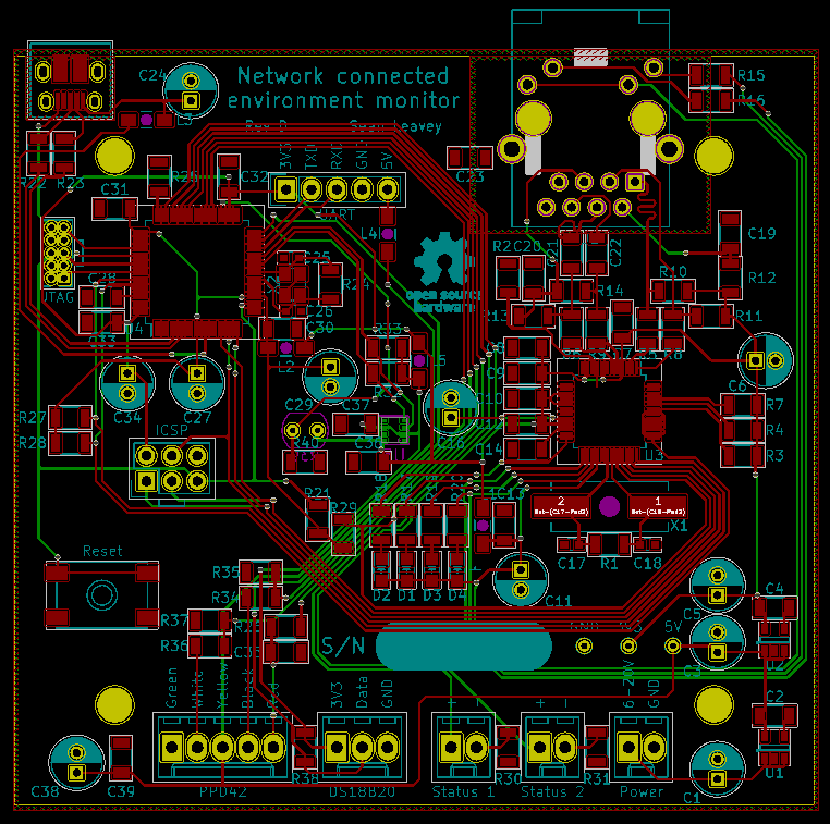
Environment sensor PCB. KiCad can look really awesome sometimes. Red and green tracks are on the top and bottom, respectively. The USB connector is top left, RJ45 is top right, the PHY is three-quarters of the way up on the left and the main microcontroller is on the middle right. The BME280 environment sensor is on the middle of the other side of the board. The dust sensor plugs in to the bottom left socket.
I chose an Atmel/Microchip ATmega32U4 for the main microcontroller, which I have prior experience with. It has enough memory to hold a large networking library and has the nice advantage of a USB controller on-board so that you can easily talk to it and power it from a standard cable.
For the network stack, I took the convenience of using Wiznet's ioLibrary which deals with the nuances of DNS and DHCP for you in order to send payloads over the network.
The dust sensor is the Shinyei PPD42NS PM2.5 sensor, available on eBay. There is also a reverse engineering of the (very simple) schematic available from Tracy Allen. This shows that it is feasible to provide a different voltage on one of the pins to get more sensitive readings of smaller particles, which I implemented.
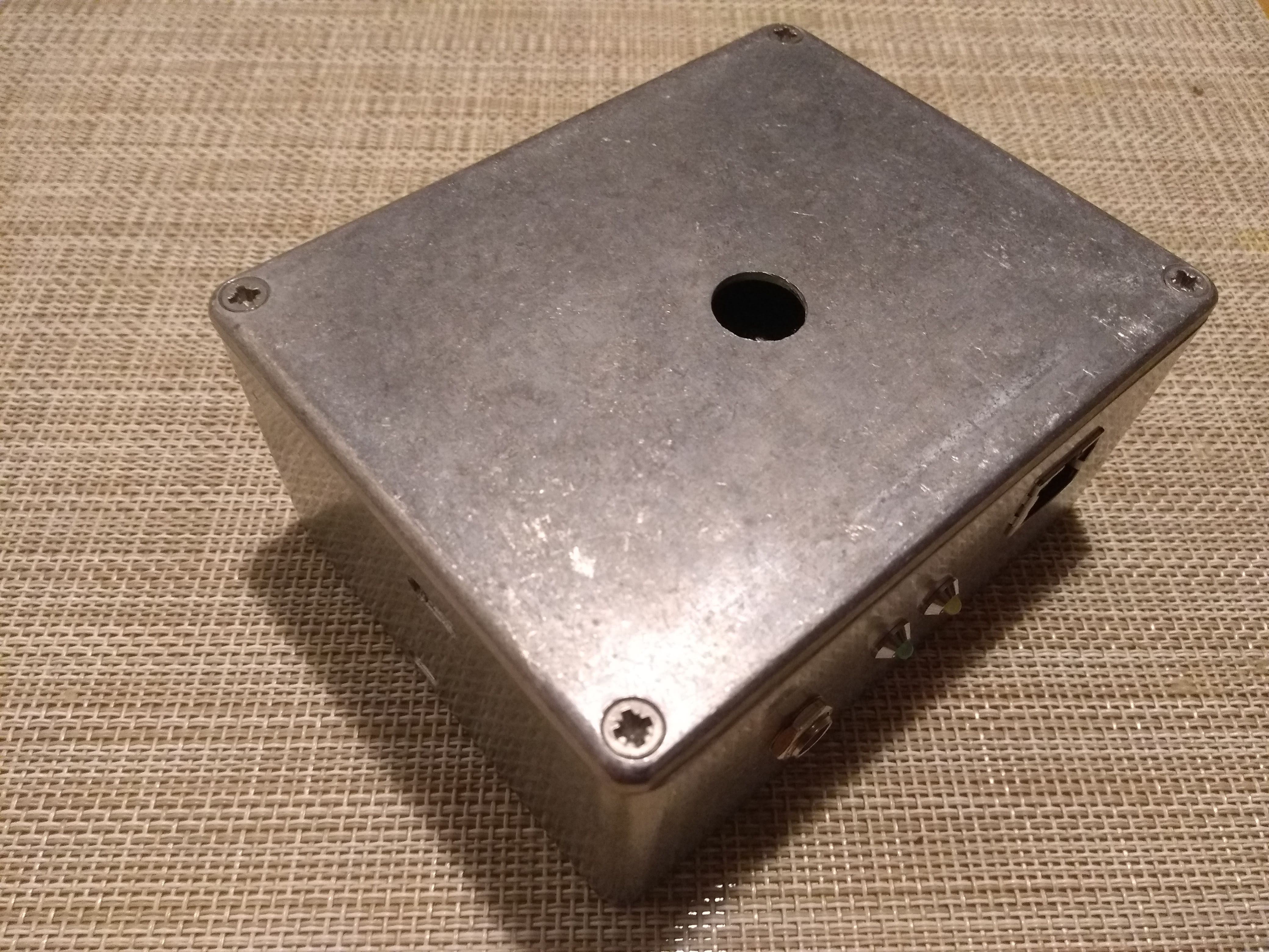
The simple enclosure I made for the circuit. There are two gaps on one side to allow air flow through the dust sensor. A resistor in the dust sensor creates convection through a channel where particles scatter incident light from an LED onto a photodetector.
The light sensor is a standard light dependent resistor read by the microcontroller. The other environment readings are made by the tiny Bosch BME280. In hindsight, this was a bad choice as its self-heating is quite high and it must be placed far from the hot parts of the circuit. Since I didn't really care much for energy efficiency (since it was anyway to be wired to an ethernet cable), the circuit produces somewhere in the region of 0.5 W of heat which significantly alters the accuracy of the sensor - not helped by my enclosure (below) - giving readings up to 12°C higher than they should be! This also affects the humidity readings, of course, rendering this aspect of the circuit a bit useless. If I were to redesign this circuit I would put the sensor far from the rest of the board, and in separate air and with isolated copper. You live and learn.
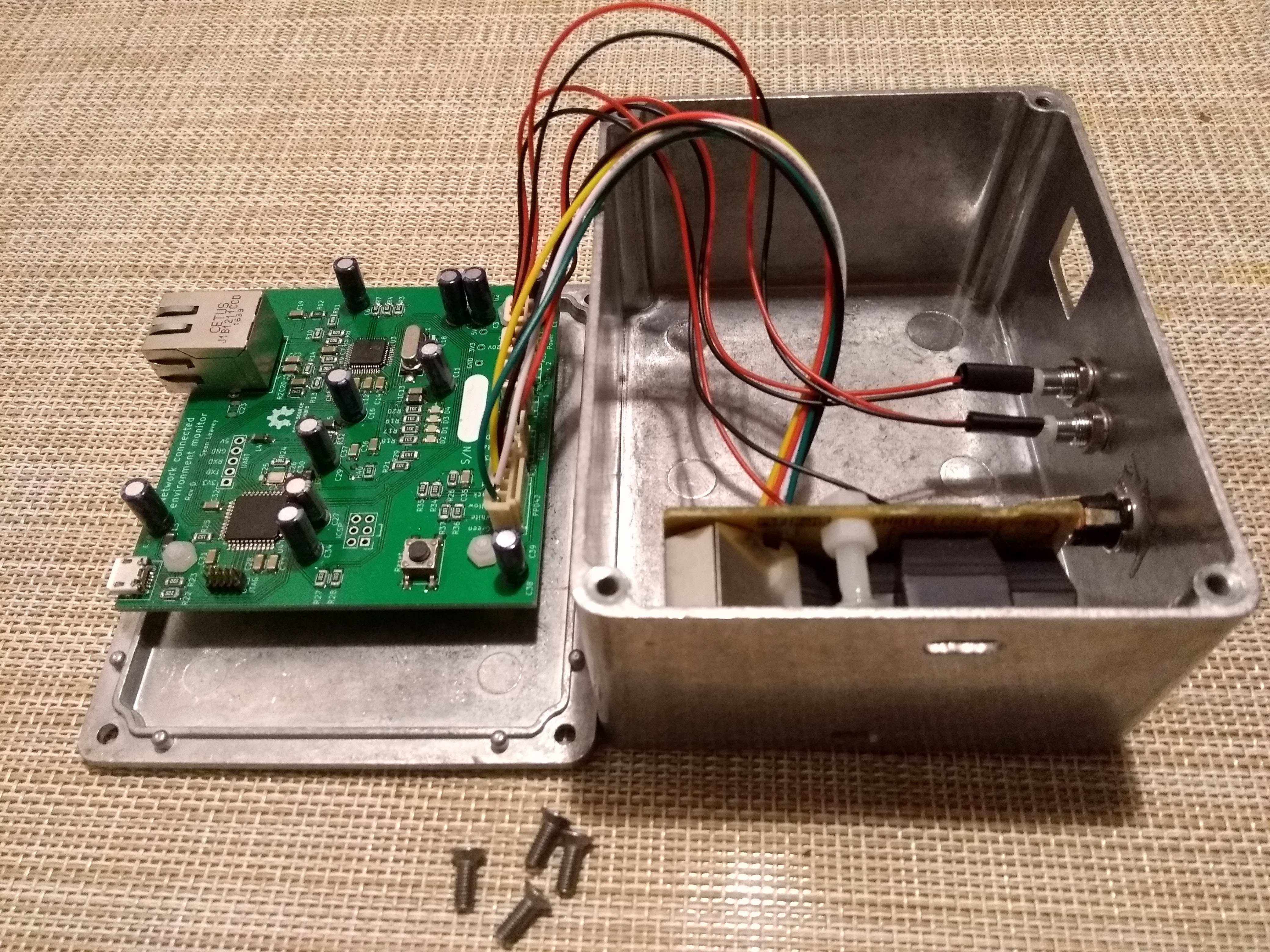
Inside the enclosure. I took the unconventional step of putting the circuit on the lid of the enclosure, and drilling a hole underneath where the temperature/humidity/pressure and light sensors are. The idea was to keep the sensors away from the microcontrollers and dust sensor, which all produce lots of heat, but this didn't really work as the temperature and humidity readings were still wildly inaccurate.
I wouldn't build this again without making modifications due to the sensor inaccuracy. However, the dust readings are reasonably accurate as far as I can tell, and the light sensor can tell if the room light is on or off, which is about as much as I wanted. I have this hooked up in my office to periodically send my server the settings, just in case long term data there is ever useful. The main benefit this circuit has given me is the experience of making it work!