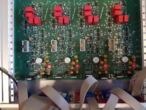
These are specialised circuits to drive "BOSEMs" used in interferometer test mass suspensions. BOSEMS contain an LED shining light onto a "flag" - a rectangular card that blocks incident light - attached to a suspended test mass used in laser interferometers. The light transmitted past the flag is sensed by a single element photodiode. A nearby voice coil is used to feed back to the flag position to keep it static in the presence of external disturbances, reducing the coupling of ground motion to the test mass.
The BOSEM LED needs a stable current so the light power is constant, otherwise fluctuations in power could be mistaken for fluctuations in flag position. The circuits here therefore provide a stable current source, photodiode readout and coil driver together in one package. Extra features include various diagnostic readouts and error detection mechanisms.
The current driver is based on the Libbrecht-Hall design. The coil driver is adapted from an electron microscope driver from the Art of Electronics, 3rd Edition. The error checking circuits are my own design. The inputs and outputs interface with the control system we use in the lab.
Since BOSEMs are used only in LIGO and the AEI 10 m prototype, these circuits are not likely to be directly useful to anyone else; however, the current and coil drivers and error checking circuits, all of which work nicely, may serve as useful references for others.
First generation
This is a four layer board with everything required crammed in. It was a pain to build but worked well. After using this I decided to make a new modular design to allow swapping in/out of individual channels.
Second generation
Documentation: BOSEMIO1, BOSEMDTR1
The main improvement with this design over the last is in the separation of the electronics for each individual BOSEM channel from the "common" electronics: routing of the inputs and outputs to and from the front panel, the power supply, stable voltage reference, etc. The common parts go on the "motherboard", BOSEMIO1. The electronics for a particular channel go in "daughter" boards, BOSEMDTR1. Each channel can be swapped on the motherboard without difficulity, e.g. to quickly replace a broken channel to minimise the experiment's down-time or to give a particular channel's coil driver more power.
I also fixed a few small issues identified in the last generation. One issue was quite a lot of work to hunt down, which was pickup on the photodiode signals due to the first generation's breaking of the cable shield at the front panel. The cables going to the BOSEMs are now grounded on the front panel and broken at the vacuum system where they go to the BOSEMs to prevent ground loops. This way the "loop area" which can create electronic pickup is minimised. The new design also uses only a 2 layer board, which makes soldering and desoldering easier and makes the PCBs cheaper to manufacture.
This design is probably the final iteration - it seems to work well.
