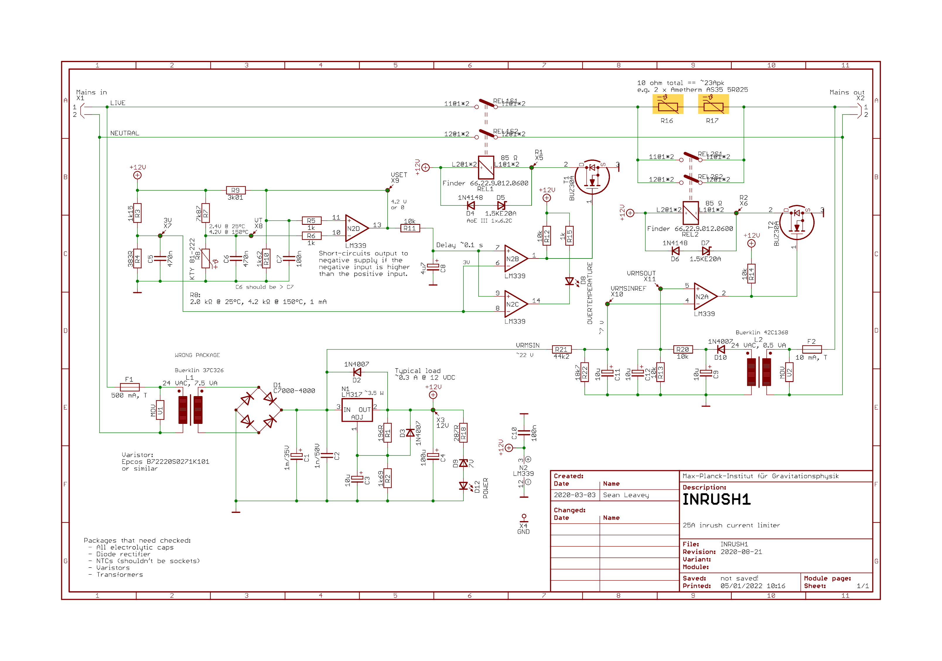
25 A inrush current limiter draft schematic.
Our DC supply racks in the lab at the AEI 10 m prototype need inrush current limiting so that the 35 A fuses in the nearby mains distribution cabinet don't trip when we turn on the approximately 20 parallel linear power supplies per rack. We bought limiters purporting to be suitable for our roughly 20 A steady state load a long time ago that claimed to limit peak current draw to 25 A, but these did not actually work, instead tripping the supply cabinet's 35 A fuses. We first tried to modify the negative temperature coefficient resistor (NTC) in these limiters to parts with higher initial resistance, which would in theory reduce the peak current draw, but the limiters' timing circuits (whose job it is to short the NTC resistor after a short delay to save power dissipation during steady state operation - which is considerable at 20 A steady state) was still too quick for the linear supply capacitors to charge and so still tripped the cabinet fuse. Given the lack of suitable alternatives to this commercial device we had to design our own.
In principle an inrush limiter can be as simple as an NTC resistor. However, these still have some resistance in steady state, and if we draw 20 A even a fraction of an ohm will cause significant heating (40 W @ 0.1 Ω). That's why most high current designs - and also the design here - have a delay circuit that triggers a relay to short the NTC shortly after switch-on to avoid its heating loss. The delay needs to be long enough for the inrush current to stop (in our case, for the linear power supplys' capacitors to become charged, transformers to be in steady state, etc.) but short enough to avoid significant heating in the NTCs.
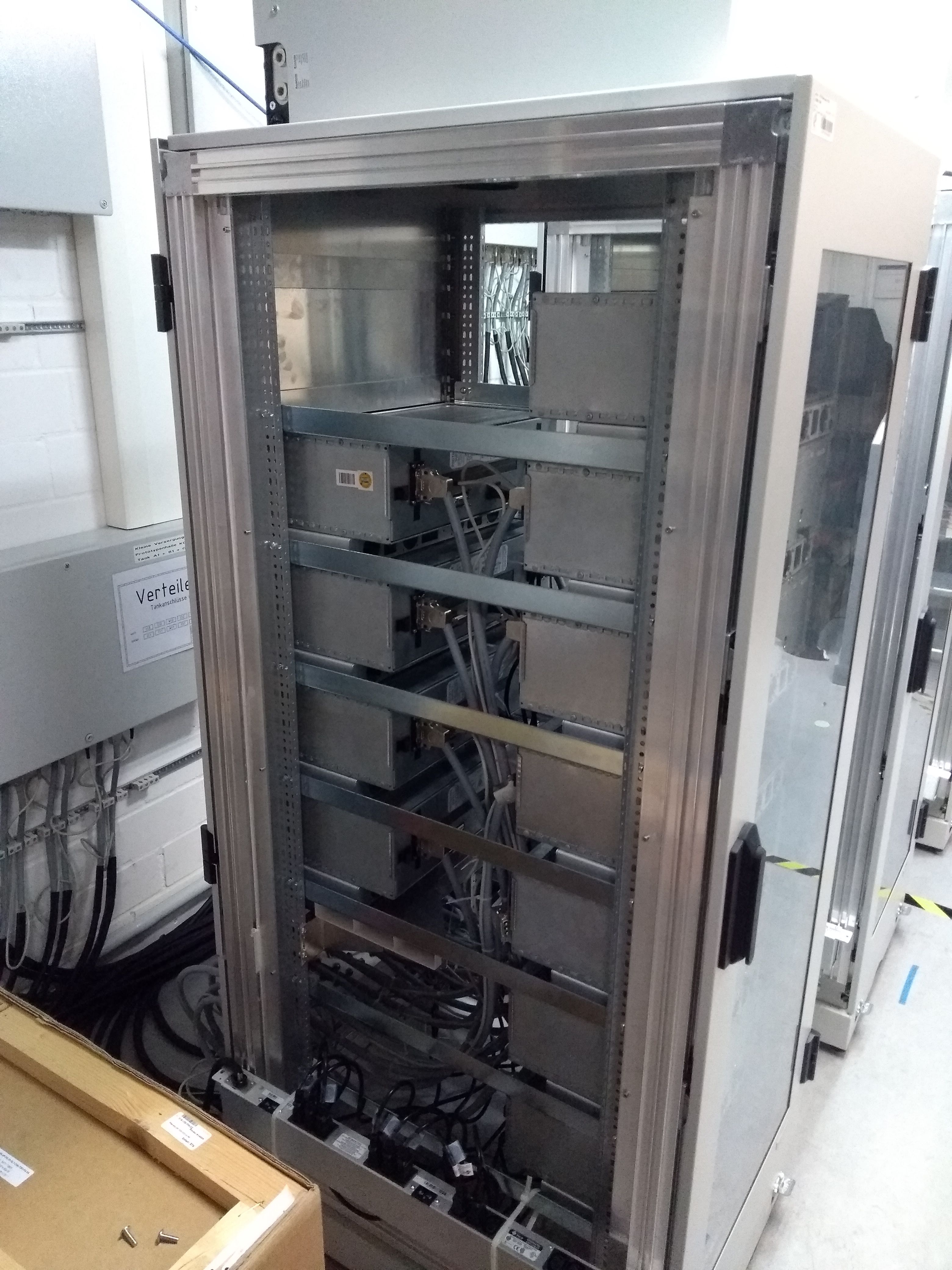
One of the three DC supply racks with ~20 linear power supplies each.
In discussion with colleagues I decided to use a linear regulator to produce the voltage required to actuate the relay. While the smaller form factor provided by a switch mode power supply could have helped, we didn't trust their long term reliability. We also decided to have an overtemperature detector which will trip the output if the temperature on the NTCs gets too high. This requires careful tuning because part of the normal operation of the NTCs is for them to get hot and drop their resistance. The overtemperature cut-out is a fail-safe in case they get too hot (e.g. due to degradation, a short, or too much load), so we don't potentially start a fire inside the racks (at least from this mechanism!).
The operation of my design is roughly as follows. Most of the resistor values etc. are not yet defined as they rely on the relays we choose, which in turn depends on the mechanics, limited by available space. Since I haven't yet built this, these values aren't final. The delay circuit capacitor value also needs tuned during commissioning due to the real NTC tolerance.
- When there is no power, the left relay is open and so no current can flow to the output (to the DC supplies).
- When power is provided:
- The relay is initially still open until the power supply rail rises above the left relay's must-operate voltage (~70% of the coil rating).
- Transformer L1 drops the mains down to some manageable level (e.g. 30 Vpp). The capacitors and LM317 regulator convert this AC into 12 VDC.
- The pull-up on the output of N2B creates a gate-source voltage at the
N-channel MOSFET T1 (BUZ30A) and so provides 12 VDC across the left relay
coil.
- The left relay contacts short together immediately, allowing current to flow through the NTCs R16 and R17 to the load. The NTCs initially limit the current to around 240 Vpk / 10 Ω = 24 Apk. As they heat up, their resistance drops and they no longer limit at 24 A.
- A transformer sensing the voltage on the load side is used to determine when to short out the NTCs. As soon as the capacitors in the DC power supplies (i.e. the load) are charged to some significant amount (probably around 70%) the voltage difference between input and output will be small, which will trigger the output of N2A back to floating, allowing the pull-up via R14 to trigger T2 and switch on the second relay to short the NTCs.
- If the temperature measured by the LM35 sensor (which will be attached between the two NTCs) gets too high, its voltage output increases and eventually N2D shorts its output to ground. This removes the gate-source bias voltage from T1 and therefore opens the left relay, cutting power to the output.
- Positive "feedback" (technically it's not feedback in the op-amp sense because of the open collector output) from N2D keeps its output shorting to ground even when the temperature drops again.
- The red "overtemperature" LED is during normal operation off. When the output from N2D is shorted to ground, i.e. when the temperature is too high, N2C stops shorting the LED allowing it to switch on. (The LED may also briefly flash on when the power is switched on, depending on timings. This is a side-effect.)
- Any time a relay opens, diodes D4-D7 shunt the flyback voltage to prevent damage to the relay. These diodes are chosen to reduce the time until the flyback is suppressed, to preserve the life of the relay contacts. This is a trick learned from the new Art of Electronics x-chapters book.
There is a new trick I used in this circuit alluded to above that will need tested in reality: the LM311 comparator N2D uses unstable negative feedback; once it trips due to overtemperature, the feedback switches to positive such that the comparator will stay tripped until its power is cycled. This is intentional so that the supplies don't yo-yo between on and off as the NTCs get hot and cold if the NTCs get too hot too quickly. This trigger relies on the behaviour of this particular comparator (it's an open-collector output type, and apparently doesn't have diodes at its input, which is a must for this trip system to work properly). I've simulated it and it seems to work, yet I've never tested it in practice - it's a new invention.
So far I've not been able to try this circuit because a bespoke mechanical enclosure must also be designed to fit into the one place they can fit in our DC supply racks, and the board will likely have to have use all available space in the enclosure, so has to wait.