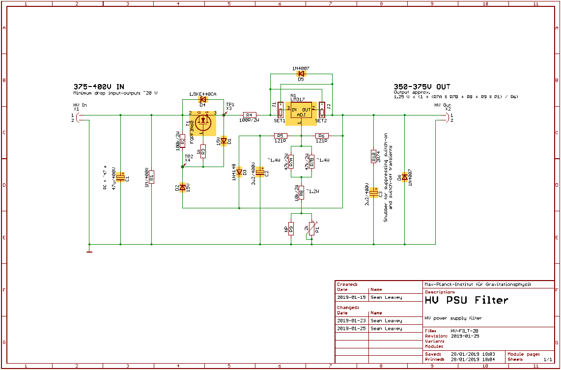
High voltage ripple and noise filter, using a low voltage floating regulator driving a high voltage MOSFET. The output can be varied depending on the choice of resistors or potentiometer setting, though low value combinations will lead to excessive power dissipation.
This is a circuit which removes ripple and noise from a power supply up to around 400 V. It uses a "Maida-style" high voltage floating regulator, and is based on a design by Pete Millett, but using a different MOSFET and suitable for higher voltages. I changed the resistors to change the voltage range, added jumpers to allow the circuit to be populated for negative voltages (using an LM337 instead of LM317, and a P-channel MOSFET such as FQPF3P50), and added an extra resistor for bleeding the 47 μF input capacitor in a reasonable amount of time to prevent shocks when disassembling.

The stuffed board (actually, this is a previous version, but not much has changed). The height is dominated by the giant, high voltage, 47u electrolytic capacitor.
There is also a large heatsink with both the FQPF3N60 and the LM317 attached; only the former dissipates significant heat (the LM317 drops only up to 15 V during normal operation) but the thermal overload shutdown function of the LM317 is useful as a temperature sensor for the FQPF3N60. If it gets too hot, it removes the voltage at the FQPF3N60's gate, shutting it off.
Most of the resistors are power resistors. This photograph is of the previous version which used low voltage bleed resistors for R1 and one that I had in parallel with C3 which I removed in this version. I realised that these are only rated up to 350 V and should therefore not be used. In the schematic above I now have R1 as a power resistor rated for much higher voltage.
The large heatsink can dissipate significant heat, allowing the filter to drop large voltages: I tested it with a 50 V drop on a 3 mA load and it barely rose above room temperature. The heat is mainly dissipated in the MOSFET because the LM317 never gets more than 15 V drop across its terminals. It is attached to the heatsink anyway to take advantage of its thermal shutdown: if the MOSFET gets too hot, the LM317 will remove its gate voltage and shut the whole thing off.
The 400 V rating is limited by the electrolytic capacitors. Higher voltages are possible - up to the 600 V limit of the MOSFET - when used with appropriately rated capacitors, but these may be larger than the space available on the board. Since the whole circuit is floating, it would be easier to just chain two of these together in series to get higher voltages.
The noise measured with an oscilloscope over 10 s is shown below, with and without in this case a 400 V supply attached. It seems that most of the noise comes from the oscilloscope itself, which has input noise of around 1 mV rms, but I used a x10 probe so it shows up as 10 mV. It is unlikely the noise comes from the circuit when it is off, as it has no power; however, I don't have a high voltage probe to use with a spectrum analyser to really check this.
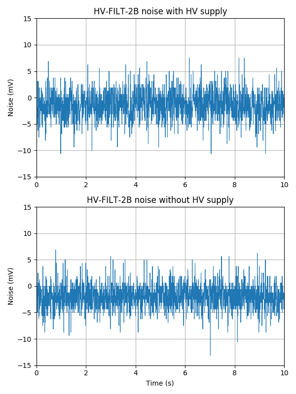
High voltage filter noise with and without high voltage supply connected. This suggests the bulk of the measured noise comes from the oscilloscope.