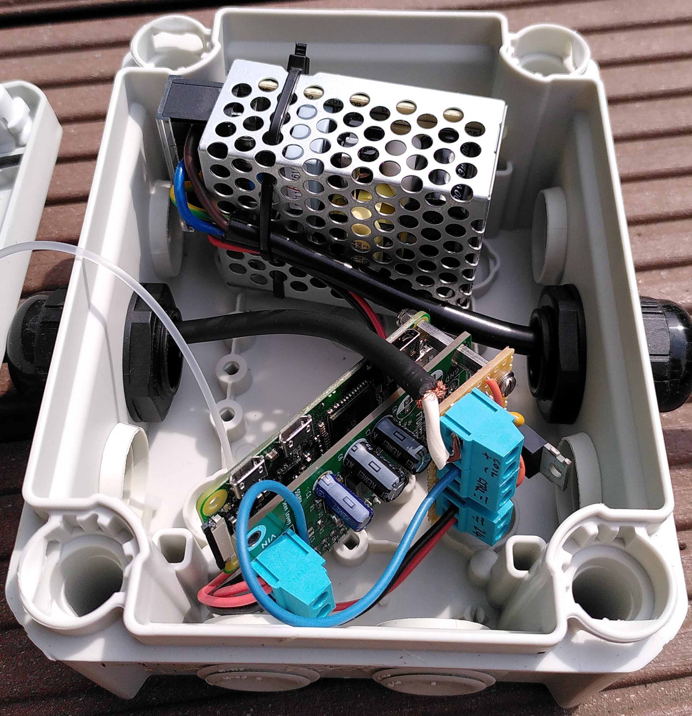
Watering system power box, containing an AC-to-DC converter providing 24 VDC for the water valve and an sslpol circuit for dropping 24 VDC down to 5 VDC attached to a Raspberry Pi Zero. The Raspberry Pi furthermore has a small board with a transistor for driving the valve's solenoid and suppressing its flyback voltage.
Sometimes you're not around to water the plants, so you need either someone or something to do it for you. I chose the latter, building a little automatic system for our balcony. In terms of hardware, it consists of a power supply, point-of-load converter, Raspberry Pi, valve solenoid driver, water valve, water supply and water pipe with nozzles going to the plants. Software-wise, it uses a simple systemd service running with a timer on the Pi.
Hardware
The hardware consists of the electronics to control and drive a water solenoid valve connected to a hose pipe to let water propagate to a series of commercial spray nozzles (Gardena Micro-Drip system). Since it's going outdoors, it will be subject to rather large temperature variations (40-60°C inside the enclosures when in direct sun, and perhaps down to -10°C if I'm too lazy to pack it away in winter), so some careful choice of components and weather-proofing is required.
Enclosure
Since these circuits are going outside in all weather, I used IP66 rated waterproof and sunlight resistant cases from my local big-box store. They cost around €5 and €8 for the smaller and larger ones, respectively. These boxes are nice because they have removable covers on the sides to let you feed cables and pipes in and out, reducing the amount of milling required.
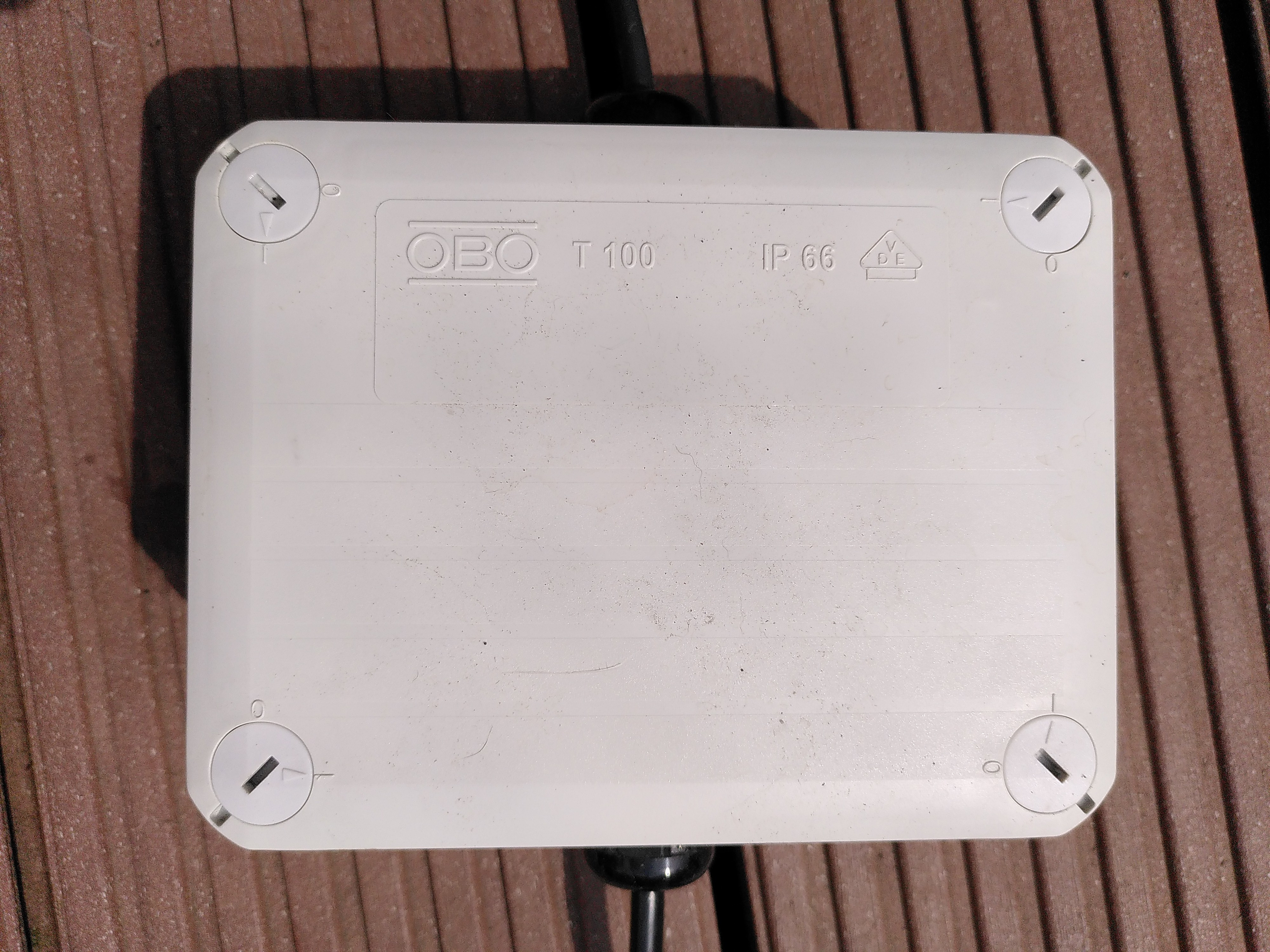
IP66 enclosure for housing the electronics (there are two of these in total, one smaller and one larger).
Water solenoid valve
I got the water solenoid valve from RS. It opens the valve, letting water through, when 24 VDC is applied to the terminals (doesn't matter which way round). These are commonly used in washing machines but they works well for watering systems too. It has a 3/4" garden hose adapter on the input side, and a 10 mm diameter nozzle on the output side.
AC to DC converter
I used a Mean Well 15 W, 24 VDC embedded power supply to provide power for the water valve solenoid and the point-of-load converter.

Power supply enclosure with connected Schuko mains plug. Mains power is provided to the AC to DC converter, which outputs 24 VDC fed to the point of load converter and valve solenoid driver.
Point of load converter and Raspberry Pi Zero
I used one of my sslpol circuits with the header installed to connect a Raspberry Pi Zero. This directly powers the Raspberry Pi by providing it with 5 VDC on its header such that no external USB power supply is needed. The input to the sslpol circuit is the 24 VDC supply also used to drive the water valve.
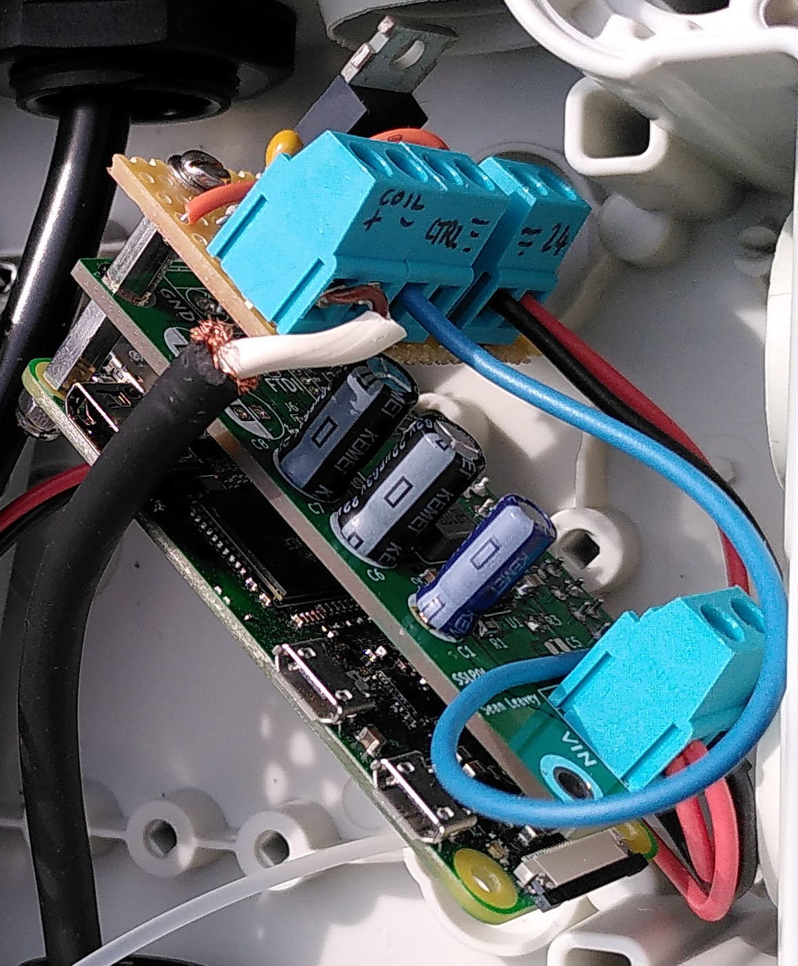
Raspberry Pi Zero, sslpol and valve solenoid driver strip board.
Valve solenoid driver
I didn't make a printed circuit board for this part, but just used some strip board. It's a simple transistor circuit, with the valve's solenoid connected to 24 VDC and the transistor's collector. I added a diode in parallel to the solenoid to suppress its back emf when switched off. Meanwhile, the transistor's emitter is grounded, and the base is connected via a resistor to a Raspberry Pi GPIO terminal. I used something like 1k, but the value isn't so important as long as your transistor's hFE is high). I added a high value (100k) resistor to ground to prolong the transistor's life in case the GPIO pin goes bonkers, and a small capacitor (100n) to help debounce the Pi's switching.
The blue wire in the picture (connected to the screw terminal labelled "CTRL") is soldered to one of the GPIO pins on the Raspberry Pi header, to allow the Raspberry Pi to control the water valve's solenoid.

Watering system sslpol board and valve solenoid driver.
Putting it all together
I put the AC to DC converter and control electronics into the larger one, using cable glands to allow the power supply cables in (230 VAC) and out (24 VDC) whilst keeping the elements out.
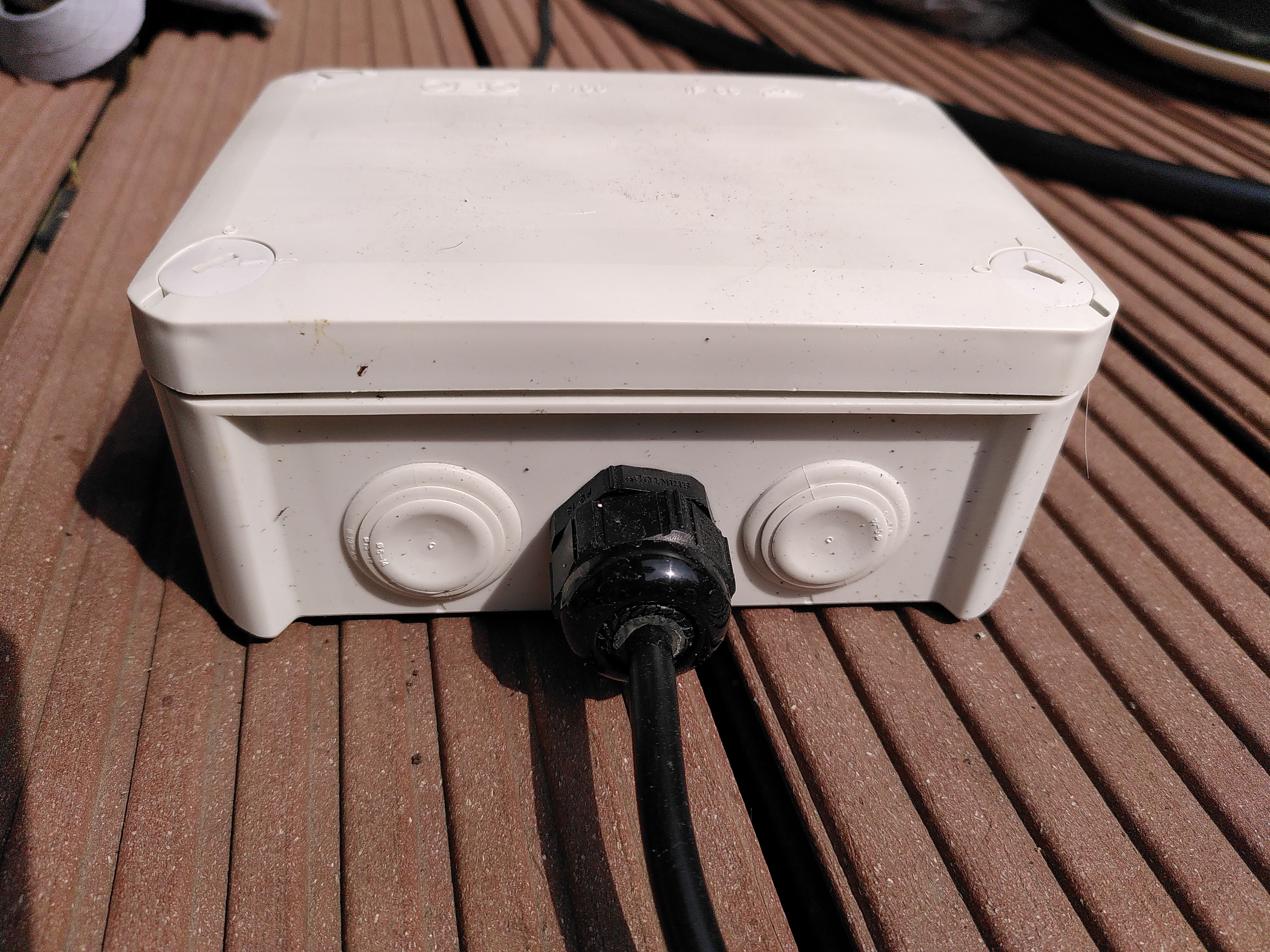
A cable gland on the side of one of the IP66 enclosures.
Into the smaller one I placed a water solenoid valve. I attached a water hose adapter to the input side of the valve, poking through one of the holes, and on the output side I attached 10 mm diameter clear pipe routed to the outside and used a cable gland to hold it.

The 3/4" hose connected to the water solenoid valve enclosure on the input side.
The 10 mm pipe connects, using an adapter, to the black 13 mm pipe used by the rest of the watering system.

The water valve solenoid, and hose and water distribution pipe adapters in the IP66 enclosure. This receives the 12 VDC supply from the power supply enclosure, actuating the solenoid to let water from the hose on the left into the black pipe on the right.
Note the water connections in the box need to be tight fitting with jubilee clips and PTFE tape to provide extra leak protection. When I first built this I skipped the tape and the enclosure started to slowly fill up with water - not good for the solenoid!
The black pipe watering system distributes the water to various corners of the balcony using first wide 13 mm pipe and then smaller 4 mm pipe to which numerous spray nozzles are attached, providing water to each plant. I used Gardena Micro-Drip system pipe, adapters and nozzles for all this, but you can get cheaper (and probably worse quality) systems on eBay.

The black 13 mm pipe distributing water to the plants. There are small junction boxes which split some water into thinner 4 mm pipe to go to individual corners of the balcony.
A spray nozzle near a happy tomato plant.
Software
The software is rather simple: just a small script to turn on a GPIO pin for a fixed time then switch it off again, and a systemd service and timer to run the script at a certain time of day.
The above approach assumes an environment with systemd and the Python GPIO library. These are both available by default on Raspberry Pi OS, which is what I used here.
Raspberry Pi boot configuration
To prevent the GPIO pin turning on at boot, ensure it's set to an output with pull-down by editing /boot/config.txt to add:
# Ensure pin 26 (pump solenoid) is set to output and pulled low.
gpio=26=op,dl
Watering script
I created a Python script as the root user, since I wanted to use systemd's journal for logging and couldn't be bothered to configure this for non-root users. I called it water.py. Create and edit with sudo nano /root/water.py and enter:
1 2 3 4 5 6 7 8 9 10 11 12 13 14 15 16 17 18 19 20 21 22 23 24 25 26 27 28 29 30 31 32 33 34 35 36 37 38 39 | import sys import traceback from time import sleep import RPi.GPIO as GPIO SOLENOID_PIN = 26 def water(duration): # Flushing needed to make journald output show up immediately. print(f"Watering for {duration} second(s)", flush=True) GPIO.output(SOLENOID_PIN, True) sleep(duration) GPIO.output(SOLENOID_PIN, False) print("Finished watering", flush=True) if __name__ == "__main__": try: duration = int(sys.argv[1]) except IndexError: print("The first argument for this program should be the duration in seconds") sys.exit(1) except ValueError: print(f"Invalid duration {repr(sys.argv[1])}") sys.exit(1) GPIO.setwarnings(False) # Prevent "channel already in use" warning. GPIO.setmode(GPIO.BCM) GPIO.setup(SOLENOID_PIN, GPIO.OUT) try: water(duration) except: print("Caught exception:") traceback.print_exception(*sys.exc_info()) print("Shutting down gracefully") GPIO.output(SOLENOID_PIN, False) |
This accepts one argument, the watering time in seconds.
systemd service and timer
Create a systemd service called water.service using sudo systemctl edit --full --force water.service, entering:
[Unit]
Description=Water the plants
Wants=multi-user.target
After=multi-user.target

[Service]
Type=exec
Restart=no
ExecStart=python3 /root/water.py 300
KillSignal=SIGINT
The KillSignal setting will issue a SIGINT when the service is killed (e.g. with systemctl stop water) instead of SIGKILL such that the Python script can catch it (the last except block) and exit gracefully - shutting off the GPIO pin correctly.
This service is of type exec such that once it finishes the command in ExecStart it considers the service complete, in contrast to a service like a database which once started continues to run as a daemon. That means we need a timer unit to control the execution of the service. Create this with sudo systemctl edit --full --force water.timer and enter:
[Unit]
Description=Run plant watering service

[Timer]
Persistent=true
OnCalendar=08:00
OnCalendar=20:00

[Install]
WantedBy=timers.target
I specified here to perform watering at 8h and 20h each day. Customise by adding or removing OnCalendar entries.
Enable the timer on boot with sudo systemctl enable water.timer and start it with sudo systemctl start water.timer. You can verify it's scheduled to run by looking for an entry in sudo systemctl list-timers.
The water.py script is configured to run for 300 seconds (i.e. 5 minutes) in the water.service unit. This can be changed to any desired duration.
Logs can be viewed with sudo journalctl --unit water.